18
LTC1967
1967f
APPLICATIO S I FOR ATIO
U
U
U
Crest factor, which is the peak to RMS ratio of a dynamic
signal, also effects the required C
AVE
value. With a higher
crest factor, more of the energy in the signal is concentrated
into a smaller portion of the waveform, and the averaging
has to ride out the long lull in signal activity. For busy
waveforms, such as a sum of sine waves, ECG traces or
SCR-chopped sine waves, the required value for C
AVE
should be based on the lowest fundamental input frequency
divided as such:
f
f
CF
DESIGN
INPUTMIN
=
( )
"
3
2
using the same design curves presented in Figures 6, 8,
16 and 17. For the worst case of square top pulse trains,
that are always either zero volts or the peak voltage, base
the selection on the lowest fundamental input frequency
divided by twice as much:
f
CF
DESIGN
INPUTMIN
=
( )
"
6
2
The effects of crest factor and DC offsets are cumulative.
So for example, a 10% duty cycle pulse train from 0V
PEAK
to 1V
PEAK
(CF = 10 = 3.16) repeating at 16.67ms (60Hz)
input is effectively only 30Hz due to the DC asymmetry and
is effectively only:
f
Hz
DESIGN
=
=
30
6 316 2
378
" .
.
for the purposes of Figures 6, 8, 16 and 17.
Obviously, the effect of crest factor is somewhat simplified
above given the factor of two difference based on a
subjective description of the waveform type. The results
will vary somewhat based on actual crest factor and
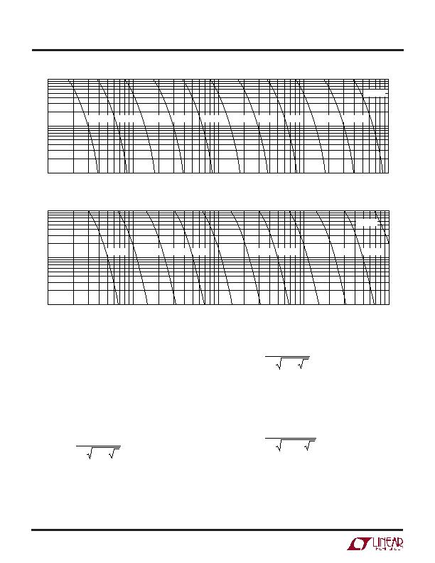
Figure 19. Settling Time with DC-Accurate Post Filter
Figure 18. Settling Time with Buffered Post Filter
SETTLING TIME (SEC)
0.01
0.1
1
10
1
0.1
10
100
1967 F18
C = 0.1礔
C = 0.22礔
C = 0.47礔
C = 1礔
C = 2.2礔
C = 4.7礔
C = 10礔
C = 22礔
C = 47礔
C = 100礔
C = 220礔
SETTLING TIME (SEC)
0.01
0.1
1
10
1
0.1
10
100
1967 F19
C = 0.1礔
C = 0.22礔
C = 0.47礔
C = 1礔
C = 2.2礔
C = 4.7礔
C = 10礔
C = 22礔
C = 47礔
C = 100礔
C = 220礔
发布紧急采购,3分钟左右您将得到回复。
相关PDF资料
LTC1968IMS8#TRPBF
IC CONVERTER RMS-DC PREC 8MSOP
LTC3100EUD#TRPBF
IC REG BUCK/BOOST/LINEAR 16-QFN
LTC3104IMSE#TRPBF
IC REG DL BCK/LINEAR SYNC 16MSOP
LTC3445EUF#TRPBF
IC REG TRPL BUCK/LINEAR 24-QFN
LTC3446IDE#PBF
IC REG TRPL BCK/LINEAR 14-DFN
LTC3537EUD#TRPBF
IC REG DL BST/LINEAR SYNC 16-QFN
LTC3541EDD#TRPBF
IC REG DL BCK/LINEAR SYNC 10-DFN
LTC3670EDDB#TRPBF
IC REG TRPL BCK/LINEAR 12DFN
相关代理商/技术参数
LTC1968CMS8
功能描述:IC CONVERTER RMS-DC PREC 8MSOP RoHS:否 类别:集成电路 (IC) >> PMIC - RMS 至 DC 转换器 系列:- 标准包装:46 系列:- 电流 - 电源:1.2mA 电源电压:±18 V,36 V 安装类型:表面贴装 封装/外壳:16-SOIC(0.295",7.50mm 宽) 供应商设备封装:16-SOIC W 包装:管件
LTC1968CMS8#PBF
功能描述:IC CONVERTER RMS-DC PREC 8MSOP RoHS:是 类别:集成电路 (IC) >> PMIC - RMS 至 DC 转换器 系列:- 标准包装:46 系列:- 电流 - 电源:1.2mA 电源电压:±18 V,36 V 安装类型:表面贴装 封装/外壳:16-SOIC(0.295",7.50mm 宽) 供应商设备封装:16-SOIC W 包装:管件
LTC1968CMS8#TR
功能描述:IC CONVERTER RMS-DC PREC 8MSOP RoHS:否 类别:集成电路 (IC) >> PMIC - RMS 至 DC 转换器 系列:- 标准包装:46 系列:- 电流 - 电源:1.2mA 电源电压:±18 V,36 V 安装类型:表面贴装 封装/外壳:16-SOIC(0.295",7.50mm 宽) 供应商设备封装:16-SOIC W 包装:管件
LTC1968CMS8#TRPBF
功能描述:IC CONVERTER RMS-DC PREC 8MSOP RoHS:是 类别:集成电路 (IC) >> PMIC - RMS 至 DC 转换器 系列:- 标准包装:46 系列:- 电流 - 电源:1.2mA 电源电压:±18 V,36 V 安装类型:表面贴装 封装/外壳:16-SOIC(0.295",7.50mm 宽) 供应商设备封装:16-SOIC W 包装:管件
LTC1968CMS8PBF
制造商:Linear Technology 功能描述:RMS-to-DC Converter Prec. 500kHz MSOP8
LTC1968IMS8
功能描述:IC CONVERTER RMS-DC PREC 8MSOP RoHS:否 类别:集成电路 (IC) >> PMIC - RMS 至 DC 转换器 系列:- 标准包装:46 系列:- 电流 - 电源:1.2mA 电源电压:±18 V,36 V 安装类型:表面贴装 封装/外壳:16-SOIC(0.295",7.50mm 宽) 供应商设备封装:16-SOIC W 包装:管件
LTC1968IMS8#PBF
功能描述:IC CONVERTER RMS-DC PREC 8MSOP RoHS:是 类别:集成电路 (IC) >> PMIC - RMS 至 DC 转换器 系列:- 标准包装:46 系列:- 电流 - 电源:1.2mA 电源电压:±18 V,36 V 安装类型:表面贴装 封装/外壳:16-SOIC(0.295",7.50mm 宽) 供应商设备封装:16-SOIC W 包装:管件
LTC1968IMS8#TR
功能描述:IC CONVERTER RMS-DC PREC 8MSOP RoHS:否 类别:集成电路 (IC) >> PMIC - RMS 至 DC 转换器 系列:- 标准包装:46 系列:- 电流 - 电源:1.2mA 电源电压:±18 V,36 V 安装类型:表面贴装 封装/外壳:16-SOIC(0.295",7.50mm 宽) 供应商设备封装:16-SOIC W 包装:管件
